After getting the ESP32 connected to WiFi and Bluetooth in the previous post, next I want to hook up some sensors to play with. Let’s start with the most common temperature sensor, the DS18B20. Its advantages are digital output, multiple devices on a single bus, and decent accuracy.
1. What You Need
- One ESP32 development board
- A DS18B20 temperature sensor module (or the bare sensor)
- One 4.7kΩ resistor (for pull-up)
- Some jumper wires
2. Wiring
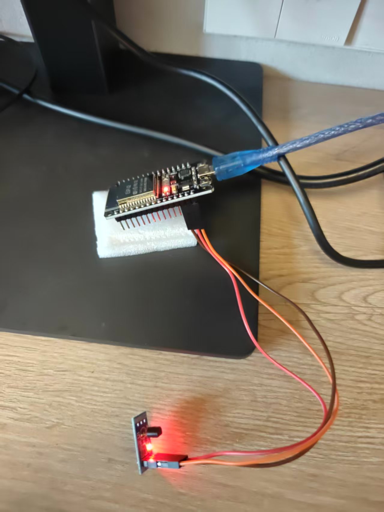
The DS18B20 comes in a three-pin package. Wire it up as follows:
| DS18B20 | ESP32 |
|---|---|
| VCC | 3.3V |
| GND | GND |
| DATA | GPIO13 |
Note: a 4.7kΩ pull-up resistor must be connected between DATA and 3.3V; otherwise the OneWire bus is unstable and devices often can’t be read.
|
Photo of the actual wiring:
3. Code to Read the Temperature
MicroPython ships with the onewire and ds18x20 modules — no extra installation needed.
|
Code notes:
scan()scans the OneWire bus for devices and returns each device’s 64-bit ROM address.convert_temp()sends the temperature-conversion command to all devices.- The DS18B20’s default 12-bit precision conversion takes about 750ms, so
sleep_ms(750)is a must. read_temp(rom)reads the temperature of the specified device.
4. Identifying the Sensor Model
Running the command below reads the ROM address and family code:
|
Output from the one I have on hand:
|
Family code 0x28 means it’s a DS18B20. If it were 0x10, it would be the older DS18S20.
5. Actual Readings
Serial output:
|
The thermometer reading as photographed:
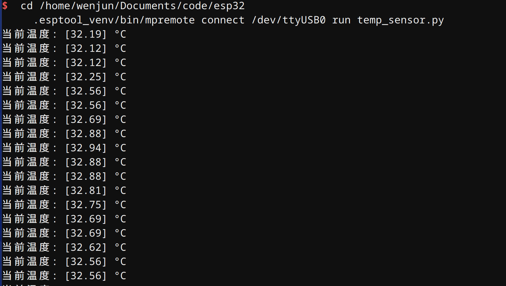
This temperature is room temperature plus the residual warmth from my fingers pinching the sensor, so it reads a bit higher than normal room temperature.
6. Common Issues
- Device not detected: first check whether the pull-up resistor is connected and whether the jumper wires are firmly plugged in.
- Temperature occasionally jumps to 85°C: this is the DS18B20’s power-on reset default; it usually means the conversion hadn’t finished when you read it. Lengthen the
sleep_mstime to 1000ms. - Multiple sensors:
scan()returns multiple ROMs;convert_temp()triggers all devices at once, then justread_temp(rom)one by one.
7. Uploading to the Blog Database in Real Time
blog-api already provides a temperature write endpoint, so no backend code is needed. The API details:
- Write:
POST https://your-api-domain.com/api/v1/temperature/realtime - Auth: header
Authorization: Bearer sk_xxx - Request body:
|
7.1 Creating an API Token
Log into the blog-api admin console and create an API Token with write permission, or just use curl:
|
Put the returned sk_xxx into api_config.py:
|
7.2 The Upload Script
Core logic of temp_uploader.py:
|
Once running, the ESP32 reads the temperature every 5 minutes and uploads it to blog-api’s realtime_temperature_records table.
7.3 Verifying the Data
Public query endpoints:
|
Just replace user_id with your actual user ID.
8. Showing It Off
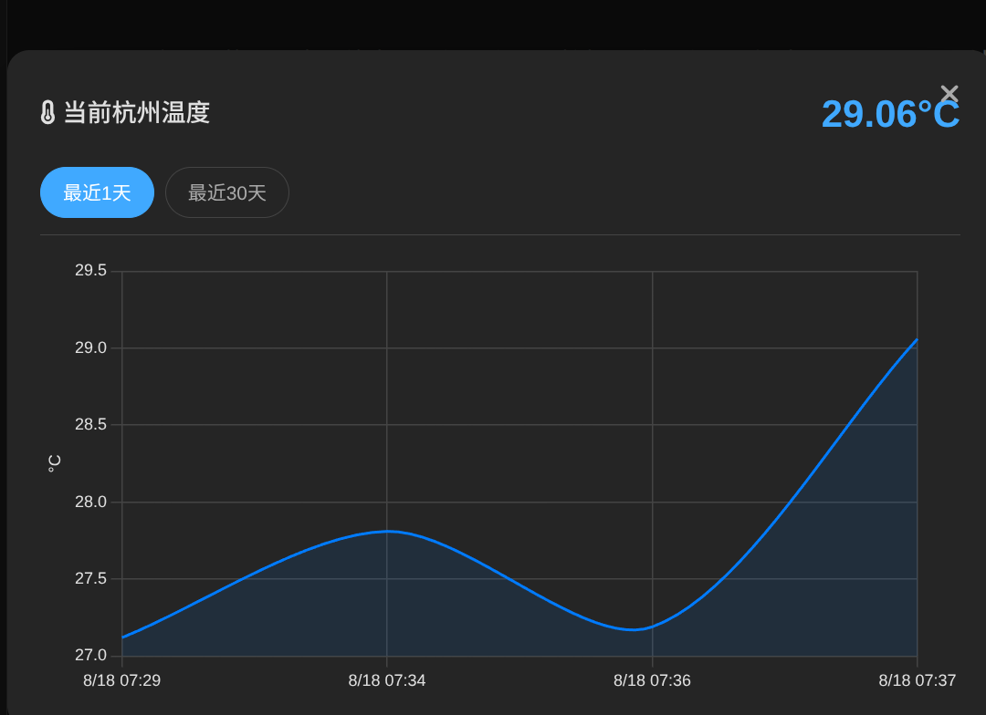
After the data was flowing, I added a “Current Hangzhou Temperature” widget to my blog homepage; clicking the temperature pops up trend charts for the last 1 day and last 30 days. The image below is the live effect, screenshotted just this morning:
9. Video Demo
Here’s a video demo of this tinkering session:
10. Next Steps
I could add a temperature card to the blog frontend that calls /api/v1/public/temperature/realtime to show the current ambient temperature, plus a line chart calling /history for the 24-hour trend — and that would make a complete wireless thermometer dashboard.
评论
0 条评论